Here is the description of each number, straight off the back of the box for the HR 2510. [My notes in brackets]
1. Mode Selector - Selects CW, AM, FM, USB, or LSB.
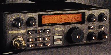
2. SWR CAL - Adjust the calabration of the SWR meter wile in the SWR CAL mode.
3. RIT Control - The Receiver Incremental Tuning control is used to fine tune the received signal.
4. RF Gain Control. - Varies the RF input to the receiver and helps eliminate strong, adjacent signals.
5. Mic Gain. - Selects a lower Mic gain level.
6. TX Switch - Locks the transmitter in the on position.
7. Meter Switch - Selects either RF/S, MOD, SWR CAL, or SWR.
8. PA Switch - Selects the PA Mode if an external PA speaker is connected.
9. NB Switch - Helps eliminate interference generated by vehicle ignition systems.
10. Dim Switch - Selects the level of the backlight of the display.
11. Scan Control - Used to scan up to 50 channels in each band segement.
12. Span Control - Select 10 KHz, 1 KHz, or 100 Hz steps for the VFO.
13. Channel ↑ ↓ - Step up or down to the next 10 KHz channel in the currently selected band segement.
14. Beep Selector - Press this switch to casue a short beep tone to be transmitted whenever you release the PTT switch. [also known as a "Roger Beep"]
15. Band Control - Selects one of four band segements.
16. F. Lock - Disables all frequency controls [except RIT] to prevent accidental changes of frequency.
17. VFO Control - Digital Variable Frequency Oscillator control used to select the desired frequency.
18. Squelch - Used to eliminate the "rushing" noise between transmissions.
19. Volume Control - Turns the unit on or off and adjusts the volume.

How to use an SWR meter on the 2510 (on anything)

1st off, let me say that I don't think the SWR meter built into most radios are accurate, or at least I've seen so many wildly inaccurate meters that I don't trust any of them. The SWR meter on the 2510 are usually close enough that it don't bother me, besides, how accurate can a segmented meter be.

1. push the "meter switch" untill the meter changes into SWR calabrate mode
2. put radio into FM mode
3. turn the SWR calabrate knob CCW as far as it will go
4. hit the "TX switch"
5. adjust the SWR calabrate knob so that the indicator is over the calabrate mark on the meter (at the high end of the meter)
6. push the "meter switch", to change into SWR mode
7. read the current SWR off the meter
8. release the "TX switch"
9. When you change frequency, you'll have to go back to step 1
10. go buy a real SWR meter, and use it instead of the built in one, so you can get a more accurate reading.
SWR Table
SWR% power lossComment
1.0:10%This is impossible, but I've seen it come close
1.5:14%Excelent
2.0:111%Not bad
2.5:1???Terrible, but acceptable. Don't go higher than this.
3.0:125%TOO HIGH, get it lower than this.
off meter100%something is really bad, look for bad coax or antenna.

The power that is lost is sent back down the coax back to the radio, which in turn causes the final (transmit) transistors to heat up even more than they usually do. High SWRs can cause early failure to the transmitter section of your radio, and at the very least make it run hotter than it could.

If you're checking SWRs in the process of adjusting an antenna, then you'll need to check the SWRs on 2 different frequencies. Say for example, you want your SWRs lowest on 29 MHz, then you'd want to check the SWRs on 28.5 MHz and 29.5 MHz (both equal distance from your 'center' frequency). You're trying to get the SWRs to be the same on both frequencies (no matter what they are, even if they're both 3:1), then it will be the lowest in the middle frequency. If the SWRs are high on the high frequency, and lower on the low frequency, then the antenna is too long. If you're converting a CB antenna to 10M ham, then you'll need to make then antenna shorter. What method you use to make your antenna shorter is up to you, but it will probably depend on the antenna itself. Many antennas are adjustable, but some won't/can't be adjusted down to 10M, in that case, you're on your own to come up with something creative to make it work.

Modifications

Depending on your model of HR 2510 it may or may not be modifiable for additional frequency range. The mods are all over the Internet, so I'm not going to repeat them here. If your radio is not modifiable, then you'll need to replace the microprocessor. If you can afford the chipswitch modification, which replaces the microcontroler on the main PLL board, then that is the best way to go. With the proper modifications it can even go to 12 meters.

HR 2510 bands
A28.000.0 MHz28.499.9 MHz
B28.500.0 MHz28.999.9 MHz
C29.000.0 MHz29.499.9 MHz
D29.500.0 MHz29.999.9 MHzsome radios
D29.500.0 MHz29.699.9 MHz
E26.000.0 MHz26.499.9 MHz
F26.500.0 MHz26.999.9 MHz
G26.965.0 MHz27.405.0 MHzCB Band
H27.000.0 MHz27.499.9 MHz
I27.500.0 MHz27.999.9 MHz
green=10 meter amateur frequencies
orange=expanded range after modification

The channel buttons on the face of the radio, and on the microphone are worthless for amateur radio. The only thing they're good for is changing channels in the CB band after it has been modified. There was a modification for the microphone buttons, published in 73 magazine a few years ago. The particular modification published used 2 ICs. The design published has design flaws. I added another IC and was able to solve the problems it had. When I can find my notes on this I'll make sure to get them in the computer, and put them up here. BTW, the chipswitch mod makes the channel buttons work as you would expect the to, another good reason to get one.

What drugs were the designers on to cause them to include a PA function on a HAM radio, and NOT put a "normal" speaker plug on the back of the radio. (They included the PA function because this was designed to be a ham and CB radio, and if you don't believe me, look on the back of the original Presidnent Lincoln box). I have drilled more holes and installed more speaker jacks in the backs of 2510s than I can even count. There IS enough room for a 1/8" speaker jack beside the stock plug. If you don't want to drill a hole in your radio, then connect the speaker jack to wires on the plug you get with the radio, and you won't have to deal with that little jumper plug any more.

Notes

The buttons on the 2510 can be hard to see where they are pointing. You can put something in the notches to make them easier to see where they are pointing. My personal favorite is a yellow crayon. Just grind it into the notch, and use a rag or paper towel to get the excess of the face of the knob (and sides if you're sloppy). I've also seen people use white-out. The nice thing about using wax is it can be removed, and nobody can even tell it had anything in it.

The Realistic HTX-100 is similar in design (not looks) to the 2510/2600/lincoln. It can even be modified to get expanded range like the 2510. I like the green backlit display on the HTX-100. The frequency knob has a spongy feel to it, unlike the 2510's stong click sound/feel. Speaking of the frequency knob...if you turn it fast enough the frequency can go backwards. The biggest thing I don't like about the HTX-100 is its lack of operating modes, I'm sorry, but I want more than just CW, and USB. No FM, no AM (and some hams DO run AM on 10M), and no LSB (which is used for packet, which is what I usually use).